자외선(UV) 레이저는 와이어 케이블 절연 재료를 표시합니다.
Sep 16 , 2022According to IOP Handbook of Laser Technology, in 1999 approximately 22,000 laser marking machines were in use in various industries worldwide. Hexa Research expects overall laser market to reach $3bln USD in 2024. It seems quite possible that in a few years everything that needs to be marked will be marked with lasers including fruits and vegetables and most definitely wires and cables.
This article describes the basic principles of UV laser marking of wires and cables for aerospace industry and its applicability to other markets.
Direct printing on wires and cables with Ultra-violet (UV) lasers has been extensively tested and accepted within the aerospace industry both by OEMs and by the end users. It is covered by several documents and standards issued by SAE International and reflected in the production specification of large and small frame aircrafts for commercial, industrial, and military use. The OEM list includes Boeing, Airbus, Lockheed Martin, Sikorsky, Gulfstream, Bombardier, Pilatus, and many others. It is also used by governmental agencies such as DOD, NASA, FAA, etc. End users employ UV laser marking machines during scheduled maintenance and repair procedures.
UV lasers leave a permanent indelible high-resolution mark on the substrate surface. To understand the phenomenon, we must consider how a laser beam interacts with material. For example, the beam can be completely reflected from a surface, as a sun ray from a mirror, or propagate unaffected, as a sun ray through clear glass window. In these cases, no trace will be left on a surface. To mark a material, at least part of the laser radiation must be absorbed directly on or near the material’s surface.
Depending on laser and material properties there are a few possible scenarios (Fig.1):
The irradiated material evaporates, leaving relatively sharp border trenches on the surface.
The irradiated material melts and spills from the inside out, creating hills and valleys in the middle of a plain.
The irradiated material heats up and produces gaseous components that react with atmospheric oxygen, depositing a product of combustion (such as soot) on the surface.
Color change. The material changes color without any other visible surface modifications.
All of the above.
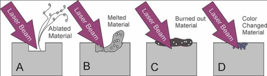
Fig.1. Laser-Surface Interactions.
Ablation is the cleanest way to alter the surface but provides low marking contrast because the affected area does not change color. Making deeper and wider marks improves legibility but reduces material integrity that is clearly unacceptable for aerospace applications. One possibility is applying additional layer of wire insolation and then selectively removing it exposing the undercoat of a different color, but this does not look very practical either.
Melting and burning marking processes are subject to long-term durability problems because the melted material and burned-out deposit may not stick well to the unaffected area. That resembles a 21st century hot stamping technique. Of course, this version is more advanced, flexible, and precise but it is still hot stamping with all its well-known deficiencies.
Color change can be an excellent solution under the conditions that it does not alter the material properties, provides sufficient contrast, good durability, and long-term stability. UV laser marking of aerospace wires and cables satisfies all these requirements.
Fig.2 shows ETFE, and PTFE insulated wires processed with Tri-Star Technologies M-100L-FG wire marking system. Well defined, legible prints stay intact even after extensive accelerated thermal aging.
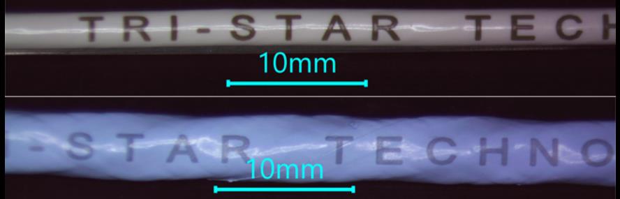
Fig.2. UV laser marking on ETFE (top) and PTFE (bottom) wires.
Marking cross sections (Fig.3) confirm that darkening zone extends 10-20um under the surface ensuring that marking cannot be altered or removed without physically destroying the top layer of the insulation.
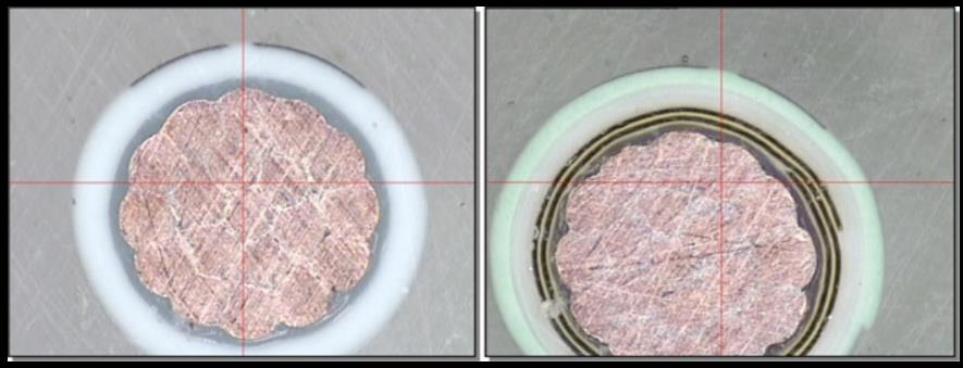
Fig.3. Marked wire cross sections for BMS13-48T10C01G022 (left) and BMS13-60T44C01G022 (right).
The question is how a light-colored polymer surface turns dark under laser exposure without burning or melting. The answer is magic substance called Titanium Dioxide (TiO2). Luckily enough, this is a commonly used pigment that wire manufacturers use to make insulation look white or otherwise light-colored, such as gray, blue, green, yellow, pink, etc.
An optical band gap around 3.1 electron volts accounts for TiO2’s intense absorption of UV radiation with wavelengths shorter than 380 nanometers. Irradiation with a UV laser permanently turns TiO2 particles from white to blue/black. The same effect occurs when those particles are embedded into a substrate. Ideally, laser radiation does not react with the base material and passes freely through the substrate surface. In contrast, the pigment particles within the substrate interact with the laser beam that modifies the particles’ structure and appearance, including color. For example, thin PTFE films are practically transparent to the UV light while small (~0.3u) TiO2particles randomly distributed through the insulation layer strongly absorb the light and change color.
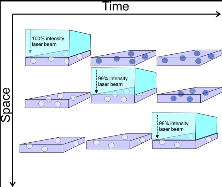
Fig.4 illustrates the process in space and time. An incident laser beam penetrates freely through the first material layer losing a small fraction (e.g., 1%) of its total energy on interaction with originally white TiO2 particles, turning them black. The same happens on the second layer and so on until most of the laser pulse energy is absorbed within the top 50-100 layers. In reality, the process is quite limited both in time and space as total pulse duration is normally below 30ns and marking depth does not exceed 50um or so.
Fig.4. Schematic representation of UV laser beam path through a transparent media dopped with TiO2 particles.
짧은 나노초 레이저 펄스는 첨가제와 주변 물질 사이의 규칙적인 열 교환을 방지하여 안료 입자 자체에 대한 구조적 및/또는 화학적 변형을 제한합니다. 분명히 이 마크는 대부분이 표면이 아니라 최상층을 통해 분포되기 때문에 쉽게 제거할 수 없습니다.
강렬한 UV 광선 노출 하에서 TiO2 입자에 정확히 어떤 일이 발생하는지에 대한 질문은 이 기사의 범위를 벗어나지만 결과적인 색상 변화는 되돌릴 수 없습니다. 예를 들어, 1990년 McDonnell Douglas Research Laboratories에서 TiO2 도핑된 ETFE 필름에 대한 UV 레이저 마킹의 장기 안정성을 조사했습니다. 마킹은 열 노화(229oC에서 770시간) 또는 모의 태양 복사(17년에 해당) 동안 거의 변화를 보이지 않았습니다. 애리조나 사막에서 UV 노출).
마킹 대비는 TiO2 농도에 비례합니다. 그러나 과도한 양은 단열재를 손상시킬 수 있습니다. 일반적으로 중량의 2-4%이면 좋은 콘트라스트를 얻기에 충분합니다. 표 1은 항공우주 산업에서 일반적으로 사용되는 와이어 구조에 직접 UV 레이저 인쇄로 달성할 수 있는 일반적인 대비 수준을 지정합니다.
표 1. UV 레이저 마킹 가능 전선 및 케이블
전선 사양 색상 절연 마킹 대비
BMS 13-48 백색 압출 XLETFE 우수
BMS 13-58 회색 PTFE 테이프 랩 양호
BMS 13-60 흰색 PTFE 테이프 랩 양호
BMS 13-60 녹색 PTFE 테이프 랩 한계
M22759/05,06,08 흰색 압출 PTFE 불량
M22759/07 흰색 압출 PTFE 한계
M22759/09,10,11,12, 20,21,22,23,28,29,30,31 흰색 압출 TFE 한계
M22759/16,17,18,19 흰색 압출 ETFE 양호
M22759/32,33,35,41,42,44,45,46 흰색 압출 XLETFE 매우 양호
M22759/34,43 흰색 압출 XLETFE 우수
M22759/80,81,82,83,84,85,86,87,88,89,90,91,92 흰색 PTFE 테이프 랩 양호
M85485/5,6,9,10 보라색 압출 XLETFE 매우 양호
M25038 흰색 PTFE 테이프 랩 불량
M27500 SP2S23 흰색 압출 XLETFE 매우 양호
M27500/20 L3T08 흰색 압출 PVDF 우수
M27500/20 P2G23 화이트 PVC/나일론 아주 좋음
M27500/22 C1G23 흰색 PVC/유리/나일론 아주 좋음
M27500/22 SP5S23 흰색 압출 XLETFE 매우 양호
M27500/24 C3G23 흰색 PVC/유리/나일론 아주 좋음
M81044 흰색 압출 PVDF 우수
다른 와이어 유형도 매직 안료를 포함하는 한 마킹할 수 있습니다. 재킷의 가장 바깥쪽 레이어에 TiO2가 있어야 한다는 요구 사항은 위에서 설명한 마킹 기술의 주요 제한 사항입니다. 대부분의 응용 분야에서 TiO2는 백색 착색제로 사용되며 UV 레이저 조사 시 검게 변합니다. 따라서 밝은 색상의 와이어만 읽기 쉽게 각인될 수 있습니다.
와이어의 나머지 부분은 그림 1에 묘사된 다른 메커니즘을 통해 레이저로 표시할 수도 있습니다. 그러나 이러한 표시는 예를 들어 흰색으로 변하는 다른 마술 안료를 찾지 않는 한 엄격한 항공 우주 표준을 준수하지 않을 가능성이 큽니다. 녹색 레이저 노출 시 검은색에서